Documentation > Instruction Manuals
|
Level Crossing Controller - 2.01.010
Introduction
The Level Crossing Controller (2.01.010) is designed to automate level crossings and can handle a pair of boom barrier motors, a pair of level crossing lights and
two IR train detection sensors. The controller can be used with our nControl™ train automation software or stand online.
Computer Controlled Operation
In computer controlled operation the controller is connected to a computer which send instructions to the controller.
The instructions can be send manually by clicking tiles or automatically with Python scripts.
Installing the Software and Driver
Start by installing the nControl™ software on the PC, mac or Raspberry Pi you want to control your layout with.
You can download the installer from our website.
The website also provides detailed installation instructions for the supported platforms.
If you're using Windows or macOS make sure the driver for the controller is installer properly.
The Windows installer should install the driver automatically.
There is a help page explaining how to check and install the driver on Windows manually.
On macOS the driver has to be installer in a separate step.
Click here for additional information on how to install the driver on macOS.
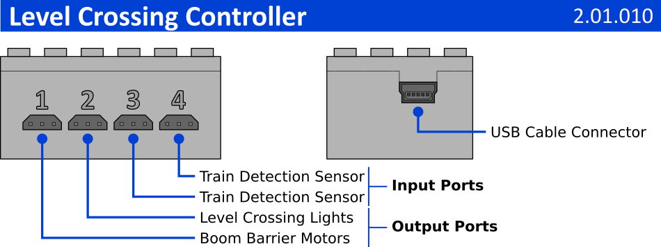
Connecting the System
The level crossing controller has 4 device ports:
Configurating the System
Click on the links below for the getting started guides:
These guide don't use level crossing controllers but all 4DBrix™ controllers have to be configured in a similar way, so you can use the exact same procedure to set-up your automation system with level crossing controllers.
Programming the Level Crossing
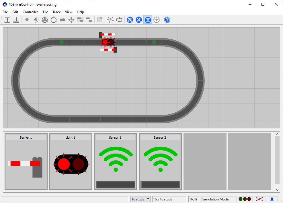
We made a demo project that controls a level crossing.
You can download the project with the button below.
The project works as follows: when a sensor detects a trail, it closes the level crossing.
When the other sensor detects the train it reopens the level crossing.
The sensor tiles have all the scripts required for the level crossing to function.
The only thing you have to do is select the correct controller/ports to which you connected your motors, lights and sensors.
You can also customize the code in the script to fine-tune the behavior of the level crossing for your layout.
 Stand Alone Operation
In stand alone operation the controller is not connected to a computer; the microprocessor of the controller will operation the level crossing.
In stand alone operation the controller is running fully autonomously, the user does not have to / cannot intervene in it's operation.
Connecting the System
The system has to be installed like for computer based operation, see above.
The only difference is the USB cable: it does not need to be connected to a computer.
It can be connected to any USB port that provides power to the controller: wall mount charger, USB battery pack, computer port, etc.
Once the controller is powered it will boot up in stand alone mode.
The controller takes a couple of seconds to boot up, once it's ready it will immediately start operating the level crossing.
Configuring the Controller
The controller has been preprogrammed to control a level crossing: detect trains, open/close the boom barriers and switch the lights on/off.
It executes the following procedure:
Fine-Tuning the Behavior / Troubleshooting
These are some tips on how to fine-tune the behavior or the controller:
Delays You have to put a sensor before and after the level crossing. When the train is detected by the first sensor it will switch on the lights and close the barriers. By adding a delay to close the barrier, the lights will blink before the barriers close which gives a more realistic effect. When the train is detected by the second sensor it will open the barriers and switch off the lights. The sensor however detects the front of the train so it might open the barrier too soon. To avoid that you can add a delay to open the barrier and switch off the lights. If you make the delay for the lights larger than the delay for the barrier, the lights will keep on flashing for some time after the barriers are open. Trimming Depending on the size of your barriers or the boom barrier motors you're using, the boom barriers might not be perfectly horizontal or vertical. Use the trimming angle to fine-tune the position of the boom barriers until they are perfectly horizontal / vertical. Sensors Sunlight and most artificial light contains an amount of infra red (IR) light. The sensor will pick that up and this might trigger false train detection events. If that's the case increase the threshold value of the sensor or reposition the sensor so that it's shaded from the external infra red source. If the trains are not detected, you need to lower the threshold value. You can visualize the amount of ambient IR light and/or the amount of IR light reflected by your trains by connecting the controller to a computer and creating a sensor tile in nControl. This will provide real time feedback on the amount of IR lights detected by the sensor and should help you get the threshold values you need. If, when the train is leaving the level crossing, the barrier open and immediately close again the sensor might be trigged by the last cars of the train. When this happens, check how long it takes between the first and last car passing in front of the sensor. The idle time should be larger than that, if not the last cars might retrigger the sensor. |
 Download Project