|
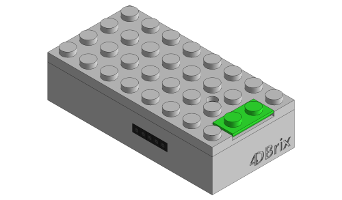
Power Brick - 2.01.100
|
The power brick provides power to the control buttons.
It takes power from a wall outlet and converts that to the power needed by the control buttons and the motors and lights they control.
|
Features
The power brick is designed to power a control panel made out of interconnected control buttons.
It has to be plugged into a wall outlet.
The power brick has an integrated power sensor that checks the power consumption. This will help you to determine whether it's safe or not to add additional control buttons.
With the on/off switch you can power up/shut down the whole control panel.
Installation
Powering the Power Brick
The power brick is powered by a wall mount AC/DC power adapter.
We offer 4 different types of power adapters:
The adapter provided with your power brick can handle 100 to 240V at 50 or 60 Hz.
Check your local power specification to see whether it's compatible with your grid.
If your outlets require a different type of plug you either need an additional
plug adapter or you need to use your own power adapter.
If you choose to use your own adapter make sure it's a 9V/2A AC/DC adapter with a 5.5 x 2.1mm jack.

|
Never use a power adapter that is not rated 9V/2A as this might damage your power brick and/or control buttons.
|
To power the brick, insert the jack into socket at the back of the power brick and then insert the adapter into a wall outlet.
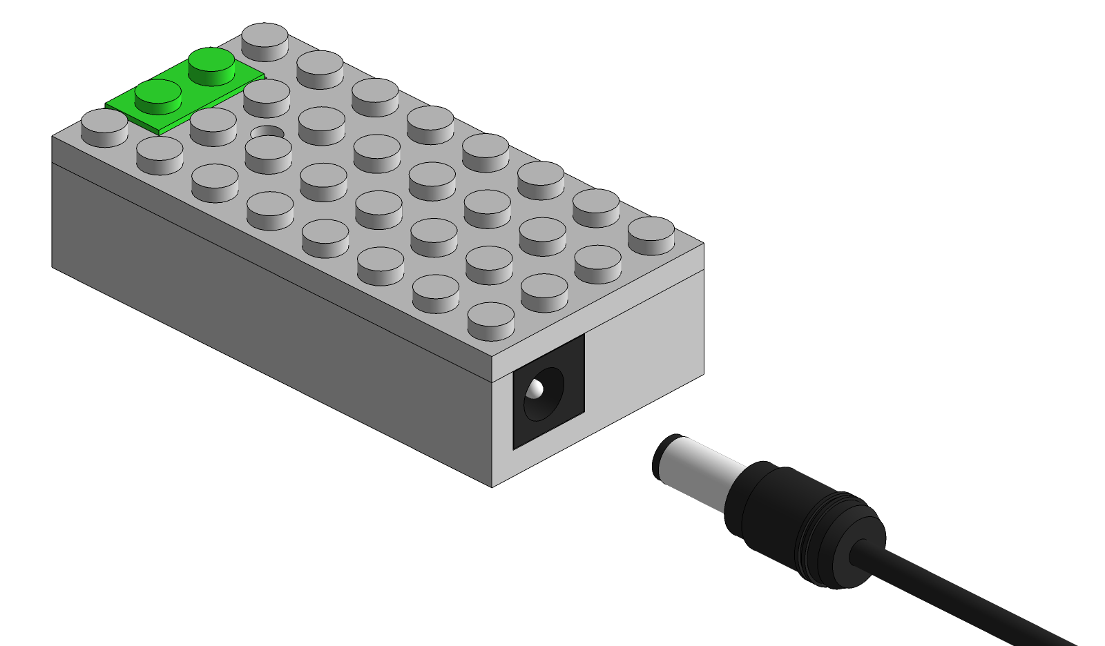
Push the green button to switch the brick on. The LED of the power brick should light up; the LED should be green, indicating that everything is fine.
If the LED is red when you switch the power brick on, shut the brick down immediately and go to the trouble shooting section of this manual.
Connecting Control Buttons
Make sure the power brick is switched off before you start connecting control buttons.
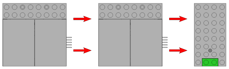
To connect a control button, simply slide the 5 pin connector of the control button into the 5 pin receptacle of the power brick.
You can also power a control button by inserting its 5 pin connector into the 5 pin receptacle of another control button that is already powered.
As such you can create a panel of control buttons all powered by the same power brick.
You can combine
servo control buttons
and
light control buttons
into one control panel, in any order you want.
There is no fixed limit on how many control buttons you can connect to one power brick.
The number of control buttons a power brick can handle depends on type of control button and the type / number of devices connected to them.
The integrated current sensor will help you determine how many control buttons you can add for your particular setup.
Current Sensor
The power brick has an integrated current sensor and continuously checks the power drawn by the control buttons and the motors and lights connected to them.
The sensor provides feedback through the LED of the power brick:
- if the LED of the power brick is green, that indicates that the power consumption is low enough to add additional control buttons.
- if the LED turns red, this indicates that you are reaching the maximal allowed power consumption and you should not add any additional control buttons.
It's OK to have a set-up where the LED is mostly green but turns red from time to time when, for example, changing a switch.
However, it's not advisable to have a set-up where the LED is continuously red.
In that case you should remove a number of control buttons so the LED remains green.
- if the LED turns red and start blinking (red-off-red-off-...), that indicates that you are getting very close to the maximal power consumption.
In fact, this is the last warning you get before reaching the actual limit and potentially damaging the power brick.
So in this case you need to shut down the system immediately and remove one, or more, control buttons.
Restart the system and check the color of the LED of the power brick.
When they are powered up, the control buttons will always switch all motors to the default position which is the equivalent of pressing the left button.
That might cause a peak in power consumption when switching on the system and cause the LED to alternate between green and red.
That is not a problem as long as the LED does not start blinking, i.e. red-off-red-off.
In that case your control panel is getting too close to maximal power consumption and a number of control buttons have to be removed.
Note that the control buttons will execute a random delay between 0 and 1 second during start up.
As such the motors are not switched to their default position at the same time and the power consumption peak at start up is reduced.
As the start up sequence is randomized it will be slightly different each time you power up your system.
One second after switching on the power brick, all your control buttons are ready to be used.
Troubleshooting
If the LED turns red when switching the power brick on:
- shut it off immediately.
- remove all control buttons and switch it back on.
- if the LED is still red: shut it down and the check whether the power adapter is 9V and compatible with your grid.
If you're using the correct power adapter, and the problem persists contact us.
- If the LED is green: switch the power brick off, connect one control button and switch it back on. Check if the LED is red or green.
If the LED turns red after adding several control buttons, than that's the number of control buttons you can use in your setup.
If the LED turns red after adding just a few control buttons, there might be an issue with the last control button you added.
Switch the system off and try different combinations of control buttons to see whether that particular control button always causes the LED to turn red.
If so, contact us.
|