Documentation > Instruction Manuals
Servo Control Button - 2.01.101
Introduction

The servo control button allows you to automate your train layout without needing a computer. It's compatible with all our servo based motors.
Features
Supported Motors and Tracks
The servo control button can handle the following servo based actuators: The control button can be used with the following tracks:
  • LEGO® PF switches and double crossover (7996-1)
  • LEGO® 9V switches
  • 4DBrix™ train track switches: tracks #18, #19, #21, #22, #33 and #37
  • 4DBrix™ decoupler: track #17
  • LEGO® monoswitch and directional monorail switches equipped with 4DBrix™ motor mount brackets
  • 4DBrix™ monorail cross switch: track #11
Modes of Operation
In order to send the correct instructions to the motors, the control buttons have to be configured for that specific device. The control buttons can be configured without the need of an external computer or programmer.
The control buttons have two modes:
  • Operational mode: in this mode you can use the buttons to control the motors in your layout.
  • Configuration mode: in this mode you can change the configuration of your control button.
When you power up the control button it will always go into operational mode.
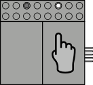
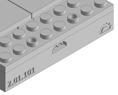
Identifying the Control Button Type
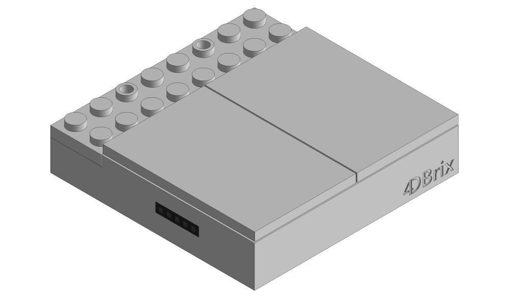
There are several types of control buttons. You can identify a servo control button by looking at the back panel. The servo control buttons have:
  • the part number 2.01.101 engraved on the left-hand side
  • have an icon of half a gear, representing the 180° movement of the servo motor, engraved on the right-hand side
Installation
This section explains how to assemble your control button system. Please read the section on how to configure your control buttons before assembling them into a control panel.
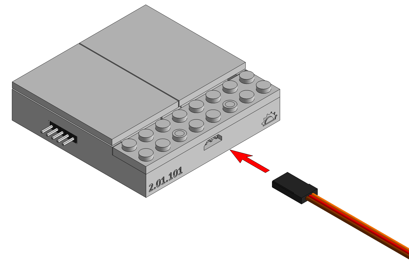
Connecting the Control Button
The control buttons are powered by a power brick. Make sure the power brick is switched off and slide the 5 pin connector of the control button into the 5 pin receptacle of the power brick. You can also power a control button by inserting its 5 pin connector into the 5 pin receptacle of another control button that is already powered. As such you can create a panel of control buttons all powered by the same power brick. You can combine servo control buttons and light control buttons, in any order you want, into one control panel.
Connecting the Motor
Configure the control button for the correct motor before connecting the motor to the control button. If the control button is not configured for the motor you're using, it might send instructions to the servo that damage the motor.
Make sure the control buttons are not powered, i.e. the power brick needs to be switched off, when you connect the motors. Connect the cable of the motor to the 3 pin connector at the back of the control button like shown on the image below; the brown wire should on the same side as the part number 2.01.101. You can use servo extension cables to move the motor further away from the control button.
Building a Control Panel
The control buttons connect to each other with 5 pin connectors. The base of the control buttons are fully anti-studded. So once they are connected you can secure the connection between the control buttons by adding LEGO® plates. The control buttons have a foot print of 8 x 8 studs.
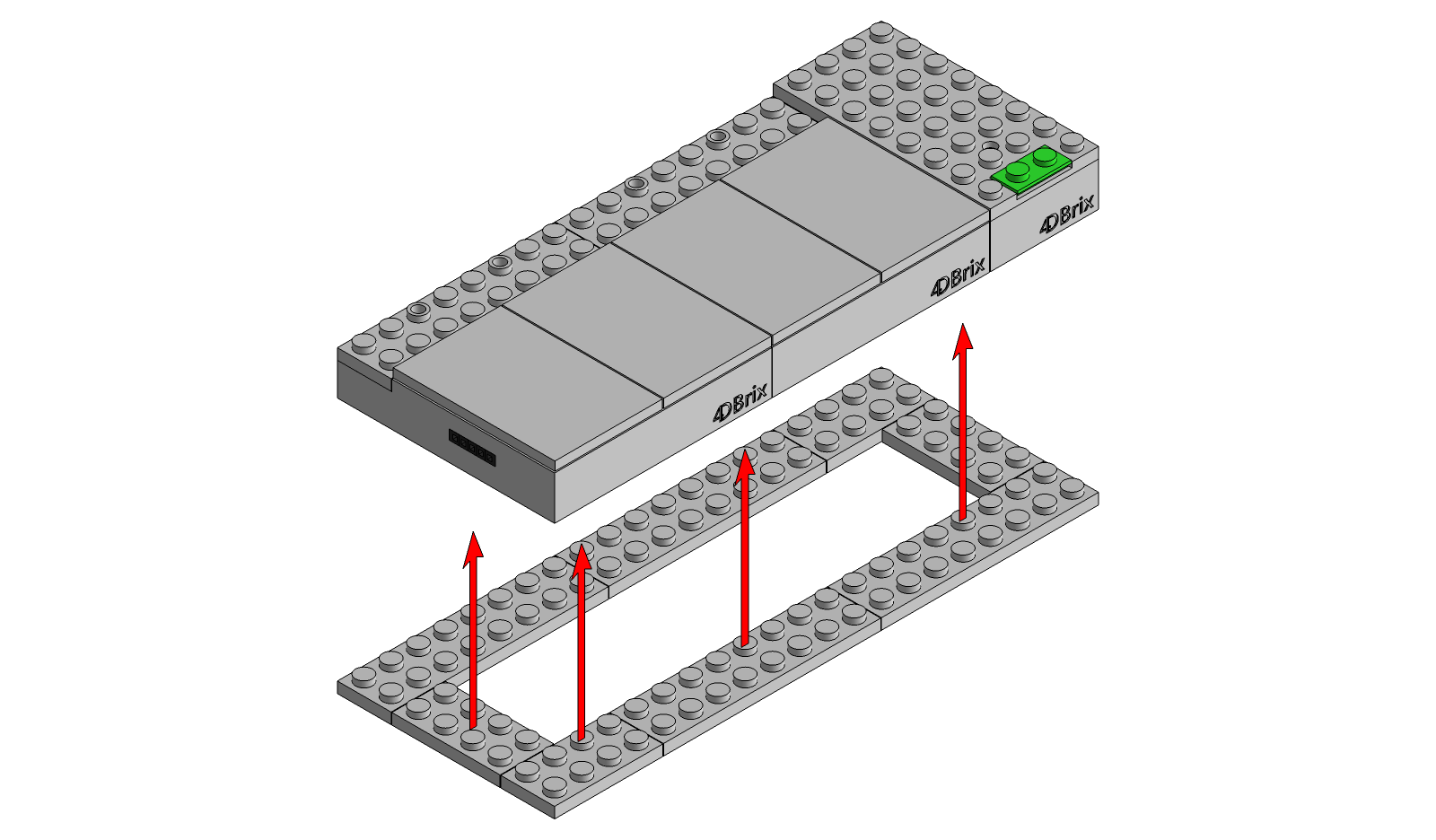
The top of the control button is studded. You can customize it by added transparent 1x1 bricks or tiles (not provided) to change the color of the LEDs. You can cover the other studs with the custom tile that is provided with your control button. Alternatively you can use standard LEGO® tiles (not provided).
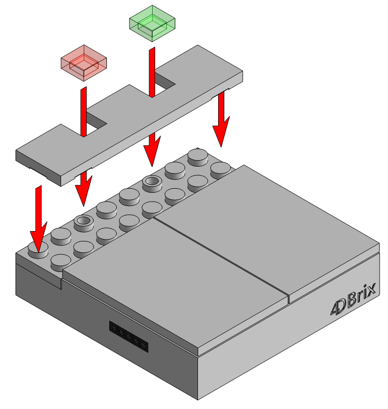
Powering Up Your System
To power up the system, push the green button of the power brick. The LED of the power brick will immediately light up. The LED should be green. If the LED is red, shut down the system and consult the power brick manual on how to resolve the issue.
The control buttons connected to the power brick will start up, one by one, in a random order. This is an intended behavior. Each control button executes a random delay between 0 and 1 second while starting up. That's to avoid that all control buttons power up at the same time and cause a peak in power consumption.
At start up, all control buttons will go to their default state: the state defined by the left button / LED. Except when the button is configured for a monoswitch, than it will start up in the stop position (both LEDs on).
Configuration
The control buttons have been programmed to handle a range of different motors on a variety of switches. Before you can use your control button, it has to be configured for the motor/switch combination you want to use it for. The selected settings are stored in the control button and will be reloaded the next time you switch the control button on.
Configure the control button for the correct motor before connecting the motor to the control button. If the control button is not configured for the motor you're using, it might send instructions to the servo that damage the motor.
The only exception are boom barrier motors. You should connect the boom barrier to the control button when configuring it.
Navigating Configuration Mode
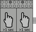
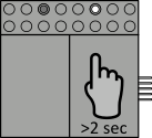
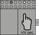
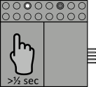
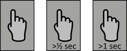
To enter configuration mode, hold both buttons down for more than 1 second. When the control button enters configuration mode, both LEDs will rapidly flash 3 times. So hold both buttons down and release them when both LEDs start flashing. 
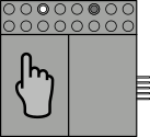
Each time the button changes mode or moves on to a next step of the configuration, both LEDs will flash 3 times.
The table below gives an overview of the operations you can perform in configuration mode.

Button Click Action
        Enter configuration mode
Select next option
Go to the next configuration step
or
Exit configuration after the last step is done
Device Selection
The first step of the configuration is to select the type of motor you want to control.
  • If you're configuring the control button for a track switch motor, decoupler or monorail servo motor, make sure the motor is not connected to the control button. This is to make sure the motors are not damaged when you power up the control button. If the control button is configured for another type of motor if might send an instruction that the motor cannot handle and damage it.
  • However, if you're configuring the control button for boom barrier motors, you should connect the motors to the control button. This is needed to find the correct trimming angles during the configuration process. Make sure the control button is not powered when you connect the boom barrier motor. Note that boom barrier motors cannot be damaged by getting incorrect instructions as they can handle the full range of possible angles.
  • Power the control button up.
  • Put the control button into configuration mode by pressing both buttons (left and right) for 5 seconds. When the control button enters configuration mode, both LEDs will blink three times.
  • Press the left button to select the device you want to control. By pressing the left button you will cycle through the supported devices. The selected device is indicted by blink sequences of the LEDs. The blink sequences have the following meaning:

    Left LED Right LED Motor Type
            Track switch motor - Standard*
    Track switch motor - Inverse*
    Decoupler
    Boom barriers
    Monorail monoswitch
    Monorail switch - Right
    Monorail switch - Left
    Monorail switch - Cross switch
    Track switch motor - Double crossover
    Push button
    Toggle button

  • Store the selected device by pressing the right button for 2 seconds. When your selection is stored, both LEDs will blink 3 times.
  • If you selected the monoswitch, pushbutton or toggle button as device, the configuration is done and you will return to operational mode. When the control button enters the operational both LEDs will blink three times.
  • If you selected another device you will enter the next step of the configuration: antibuzzing or trimming angles. Both LEDs will blink three times to indicate you have moved on to the next step of the configuration.

  • Motor Type Advaced Configuration
    Track switch motor - Standard* Antibuzzing
    Track switch motor - Inverse* Antibuzzing
    Decoupler Antibuzzing
    Boom barriers Trimming angles
    Monorail monoswitch
    Monorail switch - Right Antibuzzing
    Monorail switch - Left Antibuzzing
    Monorail switch - Cross switch Antibuzzing
    Track switch motor - Double crossover Antibuzzing
    Push button
    Toggle button
Anti Buzz Setting
The antibuzzing setting helps to reduce buzzing of the servos in the track switch motors, decoupler, monorail switch motors.
  • The button will show the current antibuzzing setting. There are 6 levels of antibuzzing, each level is indicated by blink sequences of the LEDs. You can cycle though these 6 levels by pressing the left button.

    Left LED Right LED Antibuzzing level
                Off - no antibuzzing
    Very light
    Light
    Standard
    Strong
    Very strong

  • Press the right button for 2 seconds to store the selected antibuzzing settings. This will store the selected antibuzzing setting for positioning the motor with the left button of the control button. Both LEDs will blink three times to indicate you have moved on to the next step.
  • Repeat the last two steps, this will define the antibuzzing setting for the right button of the control button.
  • Both LEDs will blink three times to indicate that the control button has left configuration mode and entered operational mode.
  • Switch the power off, connect the motor and switch the power back on. Now you're ready to control the motor in your layout.
Trimming Angles
The boom barriers might not be perfectly vertical / horizontal when the barriers are open / closed. This can be corrected with a set of two trimming angles.
  • Make sure the boom barrier motors are connected to the control buttons. If the motors are not connected, power down the control button, connect the motor and restart the configuration process.
  • Connect your barriers to the motors and place them on a horizontal surface, just like you will use them in your layout. The barrier motor will be in the closed position, so connect the barrier appropriately.
  • Press the left button to cycle through the trimming angle settings, there are 15 available trimming angles. You should see the barrier move a little bit each time you press the left button. If you pressed the left button too many times and went too far, keep going, after the 15 available trimming angles it will return to the first one and you can start over.
  • When the barrier is perfectly horizontal, press the right button for 2 seconds to move on to trimming for the open position of the barrier. Both LEDs will blink 3 times to indicate the settings have been stored and the configuration process moved on to the next step.
  • The barrier should now be in the open position. Press the left button to cycle through the trimming angles until the barrier is perfectly vertical.
  • Press the right button for 2 seconds to store the trimming angle.
  • Both LEDs should blink 3 times to indicate the button returned to operational mode.
  • You're all set and ready to control your boom barriers.
Standard and Inverse Track Switch/Motor Combinations*
A standard track switch configuration is an R motor on a right turn LEGO® switch while an inverse track switch configuration is an L motor on a right turn LEGO® switch. The list below provides a detailed overview of the of all the standard and inverse motor/switch combinations.
Standard:
  • R motor on a right turn LEGO® switch
  • R motor on 4DBrix™ switch track #18, #22, #37
  • L motor on a left turn LEGO® switch
  • L motor on 4DBrix™ switch track #19, #21, #33
Inverse:
  • R motor on a left turn LEGO® switch
  • R motor on 4DBrix™ switch track #19, #21, #33
  • L motor on a right turn LEGO® switch
  • L motor on 4DBrix™ switch track #18, #22, #37
Controlling Your Layout
Operating the Buttons
These control buttons are not mechanical switches like the 12V LEGO® controls from the eighties. They contain a microcontroller and can thus be used in a multi-functional way. There are two ways to control the behavior of the button:
  • the device for which the button is configured
  • the time you hold the button down when pressing it
Whey click a button it will send the instruction to the motor on the moment you release the button. The instruction that is sent depends on the time you held the button down. The buttons can execute three different operations:
  • holding the button down less than ½ second, i.e. just tap the button
  • holding the button down longer than ½ second but less then 1 second
  • holding the button down longer than 1 second
In this manual, these 3 operations are represented by the following icons:
The operation the button performs also depends on the configuration. This section provides an overview on how to operate the control button.
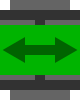
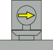
Mode 1: Track Switch Motor - Standard
If the control button is configured for a standard motor/switch combination, the switch will respond as shown in the table below. If you want the switch to respond in the opposite way, configure your control button for an inverse motor/switch combination.

Button Click Response
            or       
or

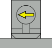
Mode 2: Track Switch Motor - Inverse
If the control button is configured for an inverse motor/switch combination, the switch will respond as shown in the table below. If you want the switch to respond in the opposite way, configure your control button for a standard motor/switch combination.
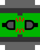
Button Click Response
            or       
or

Mode 3: Decoupler
If the control button is configured for a decoupler, the decoupler will respond as follows:

Button Click Response
           

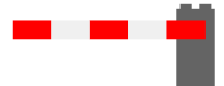
Mode 4: Boom Barrier
If the control button is configured for a boom barrier motor, the motor will respond as follows:

Button Click Response
       

Mode 5: Monoswitch
If the control button is configured for a monoswitch, the train will respond as follows:

Button Click Response
           

Mode 6: Monorail Switch - Right
If the control button is configured for a right turn monorail switch, the switch will respond as shown below. If you want the switch to respond in the opposite way, configure it as a left turn monorail switch.

Button Click Response
           

Mode 7: Monorail Switch - Left
If the control button is configured for a left turn monorail switch, the switch will respond as show below. If you want the switch to respond in the opposite way, configure it as a right turn monorail switch.

Button Click Response
           

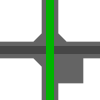
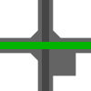
Mode 8: Monorail Cross Switch
If the control button is configured for a cross switch, the switch will respond as follows:

Button Click Response
           

motor mount position

motor mount position

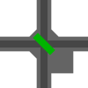
Mode 9: Double Crossover Motor
If the control button is configured for a double crossover motor the switch will respond as shown in the table below. Note that this configuration is meant for crossover motors on a LEGO® double crossovers (Set 7996-1). 4DBrix™ double crossovers use a separate motor for each switch and need to be controlled with mode 1 or 2.

Button Click Response


Mode 10: Push Button
This mode has been added for future applications.
It does not actuate the motor, it just generate a signal indicating the button has been pressed. If the buttons are connected to a computer running nControl the computer can detect the button press and respond accordingly.

Mode 11: Toggle Button
This mode has been added for future applications.
It does not actuate the motor, it just generate a signal indicating the button has been pressed. If the buttons are connected to a computer running nControl the computer can detect the button press and respond accordingly.